In this tutorial you will combine a set of interacting nodes to create a mirror effect with X3DOM.
Initially, we setup the scene containing the mirror in the X3D:
A scaled box is used to represent the 3D mirror representation. The mirroring surface is modelled as RenderedTexture which is mapped onto an IndexedFaceSet.
Note how a list of fields of the RenderedTexture, namely "excludeNodes", "background" and "viewpoint" are set using the "containerField"-attribute.
            <!-- The content of the scene to be mirrored -->
            <group DEF='MIRROR_SCENE'>
                ..
            </group>
            <!-- The pieces of the mirror -->
            <Transform DEF='mirrorTrans' translation='x y z'/>

                <!-- The box serving as the mirror's 3D representation -->
                <Transform translation='0.0 0.0 -0.3' scale='7.0 7.0 0.2'/>
                    <Shape '/>
                        <Appearance'/>... </Appearance>
                        <Box'/> </Box>
                    </Shape>
                </Transform>

                <!-- The mirror's surface -->
                <Transform translation='0.0 0.0 -0.3' scale='7.0 7.0 0.2'/>
                    <Shape id='myMirrorShape' DEF='myMirrorShape'>
                        <Appearance>
                            <RenderedTexture update='always' dimensions='512 512 4' repeatS='false' repeatT='false'>
                                <Shape USE='myMirrorShape' containerField='excludeNodes'></Shape>
                                <Background skyColor='1 1 1' groundColor='1 1 1' containerField='background'></Background>
                                <Viewpoint id='myMirrorTextureViewPoint' containerField='viewpoint'></Viewpoint>
                                <Group USE='MIRROR_SCENE'></Group>
                            <RenderedTexture>
                        </Appearance>
                        <IndexedFaceSet solid="false" coordIndex='0 1 2 3 -1'>
                            <Coordinate point='-6 -6 0, 6 -6 0, 6 6 0, -6 6 0'></Coordinate>
                            <TextureCoordinate point='1 1, 0 1, 0 0, 1 0'></TextureCoordinate>
                        </IndexedFaceSet >
                    </Shape>
                </Transform>
            </Transform>
The target of the RenderedTexture is defined by the subtree it contains. Therefore, by "USE"-ing the "MIRROR_SCENE"-group, we can target the externally defined geometry.
The mirror's shape itself has to be excluded to prevent recursion in the rendering passes.
If the viewpoint or the transformation of the mirror changes, the RenderedTexture has to be updated accordingly.
Firstly, we need to retrieve the set of vectors defining the mirror's local coordinate system in world coordinates.
    var ms = document.getElementById('myMirrorShape');
    var mv = document.getElementById('myMirrorTextureViewPoint');

    //compute transformations related to local mirror space
    var mirrorToWorldMat = ms._x3domNode.getCurrentTransform();
    var mirrorPos    = mirrorToWorldMat .multMatrixPnt(new x3dom.fields.SFVec3f(0, 0, 0));
    var mirrorNormal = mirrorToWorldMat.multMatrixVec(new x3dom.fields.SFVec3f( 0, 0, 1));
    var mirrorUp     = mirrorToWorldMat.multMatrixVec(new x3dom.fields.SFVec3f( 0, 1, 0));
    var mirrorRight  = mirrorToWorldMat.multMatrixVec(new x3dom.fields.SFVec3f(-1, 0, 0));
Next, we compute the vector from the mirror's local origin to the viewer and its length.
    //transform view vector and view point to local mirror space
    var viewMatInv = x3domRuntime.viewMatrix().inverse();
    var vPos = viewMatInv.multMatrixPnt(new x3dom.fields.SFVec3f(0, 0, 0));
    var vVec = vPos.subtract(mirrorPos);

    //compute distance between viewer and mirror
    var viewDist = vVec.length();
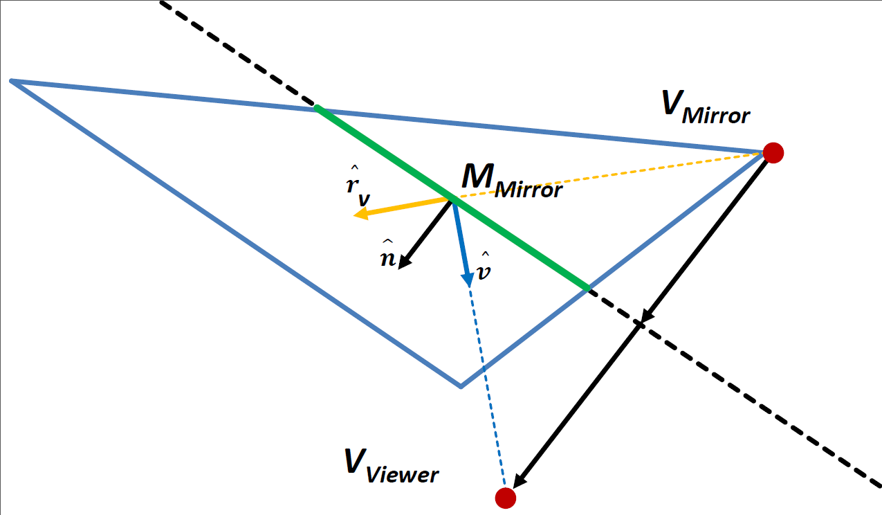
To setup the view and projection matrix for the RenderedTexture correctly, we need a list of parameters. First, we calculate the eye position by reflecting the viewer position on the mirror's normal.
    vVec         = vVec.normalize();

    //reflect view vector on mirror normal
    var reflect = mirrorNormal.multiply(2 * vVec.dot(mirrorNormal)).subtract(vVec);

    //update mirror's camera settings
    var mirrorEyeOffset = reflect.multiply(viewDist);
    var mirrorEye = mirrorPos.subtract(mirrorEyeOffset);
We can setup the viewMatrix for the mirror.
    //setup view matrix
    var vMatMirr  = makeLookAt(mirrorEye, mirrorEye.add(mirrorNormal), defaultUpVec);
    mv._x3domNode._viewMatrix = vMatMirr;
Finally, we calculate the offsets needed for the perspective frustum.
    //setup perspective frustum parameters (left, right, bottom, top, near, far)
    var sH = 0.5 * mirrorSize;

    var near  =  mirrorNormal.dot(mirrorEyeOffset);
    var left  =  mirrorRight.dot(mirrorEyeOffset) - sH;
    var right =  mirrorRight.dot(mirrorEyeOffset) + sH;
    var bottom =  mirrorUp.dot(mirrorEyeOffset)   - sH;
    var top    =  mirrorUp.dot(mirrorEyeOffset)   + sH;

    var pMatMirr  = x3dom.fields.SFMatrix4f.perspectiveFrustum( left, right, bottom, top, near, 10000.0);
    mv._x3domNode._projMatrix = pMatMirr;
The underlying geometrical concepts of these calculations and the setup of the mirror's view frustum are summarized in figure 1.
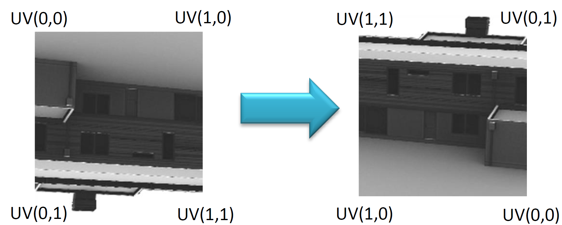
WebGL stores the rendered texture "upside-down", thus, the v-axis has to be inverted for the texture mapping.
When rendering the image from the mirror's viewpoint, it is projected onto the backside of the mirroring surface.
Therefore, we have to invert the u-axis as well. The resulting texture mapping is visualized in figure 2.

 Display example HTML file
 Download full example (.zip archive)