Within this tutorial, you will learn how to create powerful 3D manipulators (sometimes called Gizmos) in X3DOM. Such manipulators will allow you to dynamically change an object's 3D transformation, by interacting with your mouse pointer or finger on some 3D geometry. Some parts of this tutorial are also covered by X3D and VRML specification or tutorial resources, which explain the concept of pointing device sensors.
As the X3D concept of pointing device sensors, which will be used to realize the 3D manipulators during this tutorial, is pretty abstract and very generalized, it might be helpful to start off with a concrete example. In the following figure, you can see a teapot, and two different kinds of manipulators.
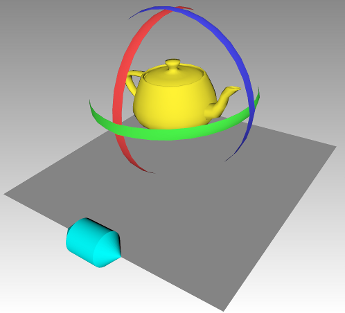
The cyan handle on the bottom left of the figure is a translation manipulator. It can be dragged to the left or right side, always following the edge of the ground plane. The teapot will then be translated by exactly the same amount as the handle. The three colored bands around the teapot are rotation handles. By dragging those, the user can rotate the teapot object around the three principal axes of the coordinate system, X, Y and Z. If you like, try out the example now, to see the manipulators in action.
We will now dive into the example more deeply, and first see how the translation manipulator was realized, using a PlaneSensor node. In X3D (and thereby in X3DOM as well), there are several kinds of nodes that are especially designed for user interaction on 3D elements. Those nodes are grouped together in the Pointing Device Sensor component. All pointing device sensor nodes have in common that they produce output as soon as the user interacts with a corresponding piece of so-called sensor geometry. A pointing device sensor node, like PlaneSensor, will consider all kinds of pointer interaction (for example, clicking a mouse, or moving the pointer) that are triggered on its sensor geometry, and produce some form of output. The sensor geometry that belongs to a pointing device sensor is the geometry that is a sibling node of the sensor node, or a descendant of a sibling node of the sensor node. Sounds complicated? Well, it is actually not that complicated. Let's come back to our example: The cyan handle is used to trigger translations on the teapot (along with colored bands around it). The 3D translation event is produced by a plane sensor, and the plane sensor uses the cyan handle as its sensor geometry. This means that, as soon as the user drags the handle, a translation event will be fired by the plane sensor, and some parts of the scene will be moved. The X3D description of the plane sensor and its handle inside the HTML page looks like the following:
    <group>
        <planeSensor autoOffset='true' axisRotation='1 0 0 -1.57' minPosition='-6 0' maxPosition='6 0' onoutputchange='processTranslationGizmoEvent(event)'>
        </planeSensor>
        <transform id='translationHandleTransform'>
            ...
        </transform>
    </group>
Inside the group node, there are two nodes: the plane sensor node itself, and the transform node that holds all the transform, shape, geometry and appearance nodes which are necessary to draw the handle. (In this case, the handle consists of two cyan cones and a cyan cylinder, but any kind of sensor geometry is possible - therefore, the actual geometry description has been replaced by dots in the above HTML snippet.) As can be seen, both of the nodes, the plane sensor and the part that holds the sensor geometry, are sibling nodes, since both have the same parent (the group node). Because of this, the cyan handle serves as sensor geometry for the plane sensor, and the sensor is triggered as soon as the cyan handle is clicked.
Let's take a closer look at how the output of the sensor is transformed into translations inside the 3D scene. The plane sensor tracks mouse motion projected onto a plane, and outputs a translation as it appears on the plane. By default, this plane is aligned with the x y plane of the local sensor coordinate system (i.e., it is affected by transform nodes above the sensor). Additionally, we can specify a rotation in the axisRotation field, which has been done for our example. By rotating the sensor plane, using the axisRotation field, we can track mouse motion projected onto the x z plane, which is the ground plane. Finally, the minPosition and maxPosition fields are used to constrain the output of the sensor in x and y direction. As can be seen in the above snippet, the second value of minPosition and maxPosition are both zero, which means that the sensor output is constrained to have always a zero value in the second coordinate. We thereby achieve that translation is solely tracked on the x axis. By setting the first values of minPosition and maxPosition to -6 and 6, we can furthermore guarantee that the translation will never move objects out of the gray ground plane.
To receive and process the plane sensor's output, we install a callback function, using the onoutputchange event. Note that we could also use the X3D ROUTE mechanism here. Please take a look at the respective tutorials for more information about ROUTES and the onoutputchange event. The following snippet shows the javascript code of the callback function that processes the plane sensor's output:
    function processTranslationGizmoEvent(event)
    {
        var sensorToWorldMatrix, translationValue;

        if (event.fieldName === 'translation_changed')
        {
            //convert the sensor's output from sensor coordinates to world coordinates (i.e., include its 'axisRotation')
            sensorToWorldMatrix = x3dom.fields.SFMatrix4f.parseRotation(event.target.getAttribute("axisRotation"));

            translationValue = sensorToWorldMatrix.multMatrixVec(event.value);

            //transform the affected sensor geometry
            document.getElementById('translationHandleTransform').setFieldValue('translation', translationValue);
            document.getElementById('rotationHandleTransform').setFieldValue('translation', translationValue);

            //transform the affected element
            document.getElementById('teapotTranslation').setFieldValue('translation', translationValue);
        }
    }
As can be seen, we first check the type of event we receive - out plane sensor can fire various types of events (for example, if it gets activated or deactivated). Having ensured that the event is a translation_changed event, we can then use the axisRotation attribute to compute a matrix that transforms the sensor output to world coordinates. The sensor output is given in form of the event.value object as a translation vector on the sensor plane. Please note that we would have to include additional transformations above the sensor node, if there would be any. However, for this simple example, it is enough to use the axisRotation of the sensor to compute the translation values in world coordinates. Having the world space translation vector at hand, we can then use it for the translation field of the affected transform nodes. This way, the teapot and the handles are translated accordingly.
You might have realized that the output of the plane sensor is always equal to the full translation from the beginning of the first drag operation. This is due to the value of the autoOffset field, being specified as 'true'. In constrast, if you set autoOffset to 'false' instead, the sensor will always output the relative translation from the beginning of the current drag operation instead. It depends on your particular application wich behavior is desired - in this case, we wanted to always update the absolute translation values of the affected objects, therefore we have set the value of autoOffset to 'true'.
While the plane sensor node can be used to map mouse motion to translation events, the CylinderSensor node maps mouse motion to rotation events. The X3D description of the cylinder sensor nodes and their respective geometries inside our example HTML page looks pretty similar as for the plane sensor:
    <group>
        <cylinderSensor autoOffset='false' axisRotation='0 0 1 -1.57' onoutputchange='processRotationGizmoEvent(event);'>
        </cylinderSensor>
        <transform>
            ...
        </transform>
    </group>
Again, the sensor is grouped together with its sibling that contains the sensor geometry. In this case, the sensor geometry is the red band around the teapot, and the sensor is used to rotate the teapot around the x axis. Of course, the descriptions of the other two bands, used for rotation around the y and z axis, look pretty similar. Although there are other possible configurations, the default behavior of a cylinder sensor is that it maps mouse motion to a cylinder of infinite height. Similar to the plane used for tracking mouse motion for the plane sensor node, the cylinder has a default orientation, which can be changed via the axisRotation field. By default, the infinite cylinder wraps around the cylinder sensor's local y axis. In this particular case of the cylinder sensor tracking rotation around the x axis, the axisRotation field is used to rotate the infinite cylinder to wrap aroung the local x axis instead. The radius of the infinite cylinder is dynamically determined for each dragging operation, as soon as the user clicks on the sensor geometry. Dragging the mouse will then lead to the cylinder sensor producing output in the form of rotation values. To process this output, we are again using a callback function, which is installed to catch the onoutputchange event. The same callback function is used for all of the three cylinder sensors (for rotation around x, y and z), and looks like the following:
    function processRotationGizmoEvent(event)
    {
        var sensorToWorldMatrix, rotationMatrixWorld;

        if (event.fieldName === 'rotation_changed')
        {
            //convert the sensor's output from sensor coordinates to world coordinates (i.e., include its 'axisRotation')
            sensorToWorldMatrix = x3dom.fields.SFMatrix4f.parseRotation(event.target.getAttribute("axisRotation"));
            rotationMatrixWorld = sensorToWorldMatrix.mult(event.value.toMatrix());

            //create an offset that applies the current rotation in world coordinates,
            //but doesn't change the orientation of the coordinate system
            currentGizmoRotationOffset = rotationMatrixWorld.mult(sensorToWorldMatrix.inverse());

            applyRotationGizmoTransformations();
        }

        if (event.fieldName === 'isActive' && event.value === false)
        {
            //incorporate the current rotation offset, interpreted globally, into the stored rotation value
            currentGizmoRotation = currentGizmoRotationOffset.mult(currentGizmoRotation);

            //reset current rotation offset to zero rotation
            currentGizmoRotationOffset = new x3dom.fields.SFMatrix4f();

            applyRotationGizmoTransformations();
        }
    }
You will probably have noticed that this function works slightly different as the one that processes output from the plane sensor. What is similar is that we convert the output of the sensor that triggered the event from local to world coordinates. Since the sensor's current rotation value is given as an SFRotation object (which is a quaternion), we convert it to a matrix before multiplying it with the value of the axisRotation field, in order to obtain the current sensor rotation in world coordinates. The big conceptual difference to the callback function used for the plane sensor is that we apply the rotation value from the sensor in the form of an offset, instead of storing an absolute rotation value. With the event.value object, we receive such offset values from the start of the current drag operation, since we have specified the autoOffset field of the cylinder sensors as 'false'. We do so by using two variables that are available throughout our javascript program:
You might be wondering at this point why we not just store an absolute rotation matrix for each axis, and then simply multiply the three transformations into a combined matrix, or store them in nested transform nodes. The reason is simply that this would not lead to the expected behavior, which has to do with a fundamental topic of computer graphics: combining transformations. A very important point, that is often misunderstood, is the fact that applying a matrix transformation changes the local coordinate system of an object. The following figure illustrates this by example:
As can be seen, the local coordinate system of the shown teapot object is rotated along with it. As long as we apply just one transformation (as in the case of the plane sensor, for example), this does not matter. But if we combine two transformations, the second transformation is always performed relative to the transformed coordinate system, after the first one. This is also what happens when you nest some X3D transform nodes (you can read more about this topic in teaching material for computer graphics, and in the X3D specification).
With this background about transformations in mind, let's come back to our example: As matrix multiplication leads to transformations being always applied in the local coordinate system, we cannot simply multiply three rotation matrices for the x, y and z axis separately. If we start with a rotation around x, for example, and afterwards apply a rotation around y, the latter one would be perfomed about the local y-axis, after the first rotation around x. Instead, what we want is that the currently dragged rotation is always applied globally. To do so, we will have to multiply the matrix that holds the currently dragged rotation offset, stored in the variable currentGizmoRotationOffset, by the last combined rotation matrix of the teapot, which is stored in the variable currentGizmoRotation. In the above snippet, the function applyRotationGizmoTransformations is used to apply the combined transform to the teapot's matrix transform node. It is called each time the rotation offset changes, and also once after the user has stopped dragging (see the check for the 'isActive' event in the above code snippet). The function is pretty simple and looks like the following:
    function applyRotationGizmoTransformations()
    {
        var teapotRotationNode = document.getElementById('teapotRotation');

        //incorporate the current rotation offset, interpreted globally, into the stored rotation value
        var transformMatrix = currentGizmoRotationOffset.mult(currentGizmoRotation);

        //set matrix value in column major format, as required by the MatrixTransform node
        teapotRotationNode.setFieldValue("matrix", transformMatrix.transpose());
    }
If you have followed this (pretty long) tutorial until this point - congratulations! You have now learned how to create powerful, interactive rotation and translation tools. Especially, you have learned how to correctly combine three world-space rotations into a single rotation matrix, which is important for many applications.
 Display example HTML file
 Download full example (.zip archive)